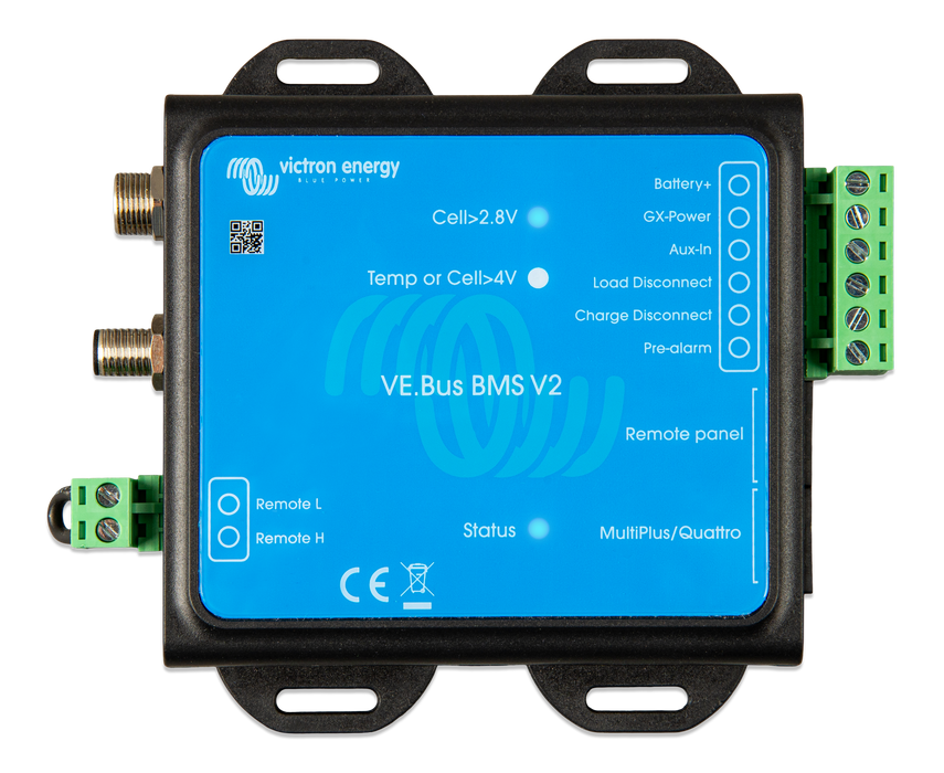
VE.Bus BMS V2
453 available | Ships in 1-2 days
💡 Is this the right product for your setup?
Downloads
Datasheets
Enclosure dimensions
System schematics
- Victron Van - Automotive - Alternator (sld)
- Victron Van - Automotive - Alternator (ds)
- Victron Van - Automotive - Multi (ds)
- Victron Van - Automotive - Solar (ds)
- Victron Van - Automotive - Solar (sld)
- VE.Bus BMS example with 3kW 12V MultiPlus 230V
- 3 Phase VE Bus BMS system 5 pin with 3xQuattro and 4x200Ah 24V Li
- MultiPlus-II 3kW 2x120VAC 12VDC 400Ah Li VE.Bus BMS Cerbo GX Touch generator MPPT Orion-Tr Smart
- US-VAN Drawing VEBus BMS MultiPlus 3KW DMC 400Ah Li Cerbo SBP 100A & 65A SmartShunt MPPT 100-50 OrionTr
- 3 Phase 5kW24V Quattro-II system VEBus BMS 2xSBP 4x200Ah Li Cerbo GX touch 50 MPPT Generator
- US Van Manual & Drawing VEBus BMS V2 MultiPlus-II 3kVA 12V 120V 60Hz
- MultiPlus-II 3kVA 120VAC 12VDC 2x200Ah Li-NG VE.Bus BMS-NG Cerbo GX Touch-50 SBP-220 generator MPPT 100/50 Orion XS BMV-712
- MultiPlus-II 3kVA 120VAC 12VDC 2x200Ah Li-NG VE.Bus BMS-NG Cerbo GX Touch-50 SBP-220 generator Lynx Distributor MPPT 100/50 Orion XS BMV-712
- MultiPlus 3kVA 120VAC 12VDC 2x200Ah Li-NG VEBus BMS-NG Cerbo GX touch-50 SBP-220 generator Lynx Distributor MPPT 100-50 Orion-XS BMV-712
- MultiPlus 3kVA 120VAC 12VDC 2x200Ah Li-NG VEBus BMS-NG Cerbo GX touch-50 SBP-220 generator MPPT 100-50 Orion-XS BMV-712
VE.Bus BMS V2 is a Battery Management System (BMS) designed to interface with and protect a single, or multiple Victron Lithium Battery 12,8V & 25,6V Smart (LiFePO4 or LFP) in systems that have Victron inverters or inverter/chargers with VE.Bus communication.
The BMS monitors and protects the batteries against over voltage and under voltage of any individual cell, and also over temperature or under temperature conditions.
If the cell voltage or battery temperature is outside of the allowable range, this is communicated to the BMS via two BMS cables with M8 circular connectors. In systems with multiple batteries, the BMS cables of each battery are connected in series (daisy chained), with the first and the last BMS cables connected to the BMS.
Based on the status of the battery or batteries, the BMS will:
- Generate a pre-alarm signal to alert of an imminent cell under voltage condition.
- Disable inverting in VE.Bus inverters or inverter/chargers via VE.Bus, and disable other loads via the 'Load Disconnect' terminal in the event of a cell under voltage condition.
- Disable charging in VE.Bus inverters or inverter/chargers via VE.Bus and disable other chargers via the 'Charge Disconnect' terminal in the event of a cell overvoltage, under temperature or over temperature condition.
The “original” VE.Bus BMS was best used in systems without a GX device.
The “next generation” VE.Bus BMS V2 has additional features such as:
- Remote on/off terminals.
- Ability to disable VE.Direct and VE.Can solar chargers via a GX device.
- Allowing control of the VE.Bus inverter/charger from multiple devices, like the Digital Multi Control, the VE.Bus Smart dongle and/or a GX device.
- Auxiliary power input and output terminals that allow a GX device to remain powered in the event of a system shutdown.


