Pylontech US5000 Quick Start Guide
This guide provides essential steps for commissioning Pylontech US5000 batteries with a Victron Energy system containing, at minimum, a Victron GX device (such as a Cerbo GX MK2 with a GX Touch display or an Ekrano GX), and a Victron inverter/charger.
Please note that this guide is not a replacement for, and should be used in conjunction with, the Pylontech Battery User Manual included in the packaging.
Required Materials
- 1-16 x Pylontech US5000 Battery Package(s)
- 1-16 x Pylontech Cable Kit (*depends on current draw potential of the load)
- 1 Victron VE.Can to CAN-bus BMS type A Cable
- 1 Victron VE.Can RJ45 terminator (Included with the purchase of a Cerbo GX)
- Appropriate Fusing
- Optional: MK3 to USB Adaptor
Quick note on racking and battery enclosures:
Pylontech produces clamping brackets for its rack-mount batteries, designed to allow up to 3 batteries to be vertically stacked. If you have purchased these brackets and wish to install them, please note that there is no need to remove the mounting tabs, as the brackets can simply be slid on from the rear. Do take note that one bracket is for the front and the other for the rear; the two are not interchangeable.
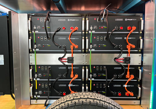
Pylontech’s ventilated and IP55-rated Energy Storage Cabinet includes all necessary hardware to mount and contain 4 x US5000 48V LiFePO4 batteries (For more, read Pylontech Racking, Accessories, and Enclosure Options).
You may fabricate or buy your own racking solution as well. The goal is to secure the batteries in place and to install them in a temperature-controlled environment. (For more on this, read How to Manage the Temperature of a Lithium Battery Bank)
Basic Commissioning Process
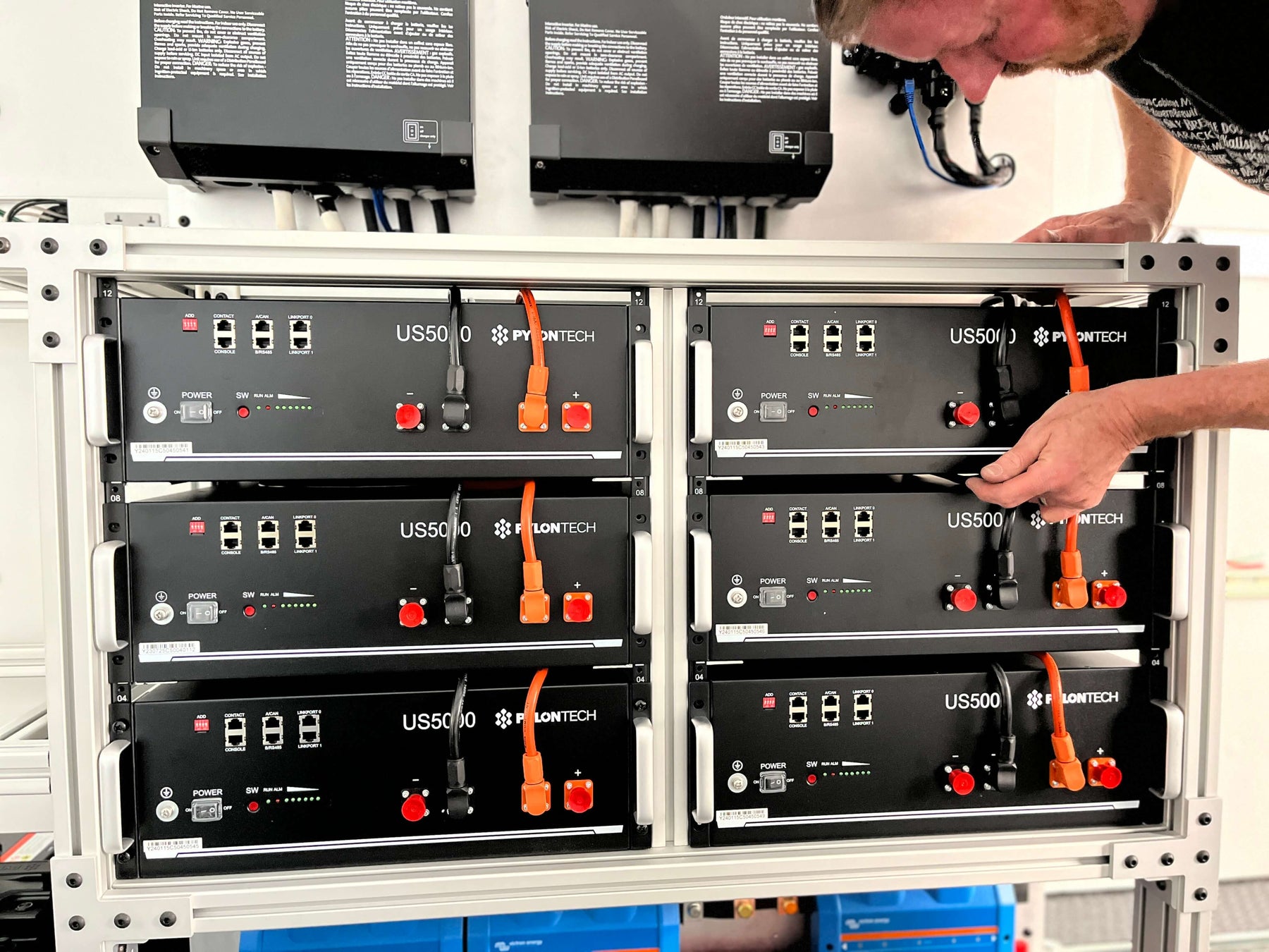
Step 1: Unbox the Pylontech battery(s) and take note of the orange and black battery jumper cables. If more than one battery is being commissioned, also take note of the short RJ45 communication jumper cable.
Step 2: Place the battery(s) in your installation location (rack, cabinet, etc). If there are multiple batteries, connect each battery to its neighbor(s) in parallel by connecting the positive (orange) Radsok terminals via the red battery jumper(s) and the negative (black) Radsok terminals via the black battery jumper(s).
Step 3: Take the “Victron VE.Can to CAN-bus BMS type A Cable” and insert the “VE.Can” labeled side into the BMS.Can port on the Cerbo GX. Place the terminator plug included with the GX device into the remaining BMS.Can port.
Step 4: Connect the remaining end of the Victron VE.Can to CAN-bus BMS type A Cable. labeled “Battery BMS Can-type A” to the A/CAN port on the Pylontech battery. If you are configuring multiple batteries, the unit that this BMS cable connects to will need to function as the “Master Battery” in the communication string described in the following step.
Step 5 (for multiple batteries): Take the RJ45 communication jumper cable included in the battery package and connect it to the LINKPORT 1 of the master battery (LINKPORT 0 of the master battery should be left open). Next, connect the other end to LINKPORT 0 of the next battery. Repeat this sequence with all subsequent batteries until the final battery in the parallel string is left with an empty LINKPORT 1. If you're wondering which battery is the master, it's always the one with the LINKPORT 0 open and should have the BMS cable plugged into the A/CAN port connecting it to the Cerbo GX.
Step 6: Open the Pylontech Cable Kit and take out the orange and black end run battery cables. The orange will function as the positive and the black as negative. Regardless of where in the DC power system these end runs are connected, they will need to be appropriately fused on the positive run with a fuse rated for at least 52V and 125A. If you are using the Victron Lynx system, these can be the 80V, 125A MEGA fuses installed on the positive bus section. Connect the orange cable to the positive DC terminal or busbar and the black cable to the negative DC terminal or busbar. Make sure the connections are tight and that the Cerbo power cables are also connected.
Step 7: Connect the orange battery end run cable to the positive (orange) Radsok terminal and the black battery end run cable to the negative (black) Radsok terminal. (Note. If the system includes multiple batteries wired together in parallel, and the anticipated loads are greater than 100A, talk to your distributor about obtaining and wiring multiple end-run cables).
Step 8: On each of the batteries, flip the power switch to the (On) position. Once all the switches are On, press and hold the red start button on the master battery for 1 second. For a system with more than one battery, this will turn on all the subsequent batteries in sequence and allow for the precharge circuit to reduce the strain on the batteries and start to charge the capacitors in the inverters. Without this sequence, the batteries will throw a warning light because the inrush of a discharged capacitor looks a lot like a dead short to the BMS.
Step 9: The system should now be powered on. Consult the display of your GX device. Check the Device List to confirm that the Pylontech batteries are recognized and enter the Cerbo settings and confirm that DVCC is forced on. If DVCC is not forced on, update the Cerbo to the latest firmware via WiFi and re-confirm that DVCC is active.

Indicator Lights Overview
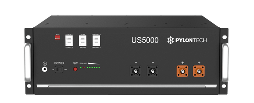
The Pylontech US5000 battery has the following lights:

Common scenarios indicated by the lights:
- Startup: All lights will briefly illuminate.
- Idle: The RUN light will briefly flash every ~3.5 seconds.
- Charging: The RUN light will be solidly illuminated, a SOC light will flash, indicating charge level.
- Discharging: The RUN light will flash every ~1.5 seconds, the SOC lights will be solidly illuminated to the current level of charge.
- Alarm: The ALM light will flash every ~1.5 seconds. The other lights will indicate their normal states as shown above. This level of alarm indicates that a condition such as temperature, current, voltage, etc. is nearing the outside limits of normal operation. Under an alarm state, the batteries are not in danger and will continue normal operation.
- System Error/Protection Mode: The ALM light will be solidly illuminated, and all other lights will be off. Under Protection Mode, the battery will refuse to accept charge/discharge. This is the battery’s way of preventing damage from an unknown/adverse condition. If multiple batteries are connected, the remaining batteries will continue operating independently of the protected battery.
Common troubleshooting scenarios:
1) Immediately after commissioning, the battery(s) go into System Error/Protection Mode.
This is most likely a communication error due to improper wiring. Check your communication jumper cables, turn all power switches off, and restart the commissioning process from Step 8.
2) Immediately after commissioning, the battery(s) are operational but don't show up on the Cerbo GX.
Check the Victron VE.Can to CAN-bus BMS type A Cable. Make sure that the “VE. Can” side is plugged into the Cerbo BMS.Can port, and that the “Battery BMS Can-type A” is plugged into the A/CAN port on the battery. Also check that the Victron RJ45 terminator is plugged into the remaining BMS.Can port on the Cerbo.
3) Some of the batteries are charging/idle while others are discharging.
Congratulations, you have discovered one of this battery’s hidden features. Chances are your batteries are experiencing no loads other than the inverter/Cerbo. Under light load conditions like this, the batteries will begin to balance themselves in relation to each other by siphoning small currents between units or idling while higher SOC units supply the load to the inverter/charger or other DC device needing power. When a larger load is applied, the process will function in reverse; the higher SOC batteries will supply power to the load until they reach equilibrium with any batteries previously at a lower SOC. This means your Pylontech battery bank is capable of balancing while discharging AND charging.
4) The ALM light is blinking.
The alarm light indicates that the battery is approaching the outer limits of normal operation. This should be considered more of a “heads up” warning than an urgent alarm. Most alerts can be viewed on the Cerbo touchscreen display for evaluation. While an alarm may indicate an issue that requires attention, the battery is still operating within acceptable parameters. For instance, the US5000 can safely handle charge/discharge currents of up to 120A. However, the system will trigger a high current alarm whenever the current exceeds 100A per battery. Remember that the batteries will disconnect and protect themselves if they encounter a situation where continued operation could cause harm.
Charging Parameters
We recommend programming your battery’s charging parameters into the inverter itself. This ensures that if communication is lost between the inverter and the batteries, we can simply turn the inverter OFF and ON, and it will start to charge our lithiums with the appropriate voltages, rather than the factory default settings. To do this, you will need an MK3 to USB Adapter and either the VictronConnect software or the VE.Configure software (VictronConnect is much more user friendly). Once connected to the inverter, program in the following settings.
- On the General tab, check the Enable Battery Monitor function is ON
- Go to the Charger tab > Charger Settings
- Change battery type to Lithium
- Ensure the Charge Curve is set to Fixed
- Set Absorption Voltage at 53V
- Set Float Voltage at 51.0V
- Set Absorption Time will be set to 1 hour
- Next, go to the Inverter tab > Inverter settings
- Set DC Input Low Shutdown to 44V
- Set DC Input Low Restart to 48V
- Set DC input low pre-alarm to 48V
Note: Make sure to double-check the float voltage after completing Assistants, and if necessary, set it back to 51.0V
For off-grid use: Ignore the 'BMS assistant required' warning.
Looking to integrate Pylontech batteries into your product or power system design?
Intelligent Controls is a technical distribution partner for Victron and Pylontech in the United States. We support professional installers and manufacturers with the equipment, tech support, and training they need to take their businesses to the next level.
To start the conversation with our team, fill our our Get in Touch form or reach out directly to mike@intelligentcontrols.io
Related Articles:
Victron’s DVCC Function Explained
How Many Pylontech Batteries Can Be Connected Together?
Battery Communication: Closed vs. Open-Loop Communications
Bad, Better, Best: Battery-Inverter Communications & Compatibility
Shop LiFePO4 batteries
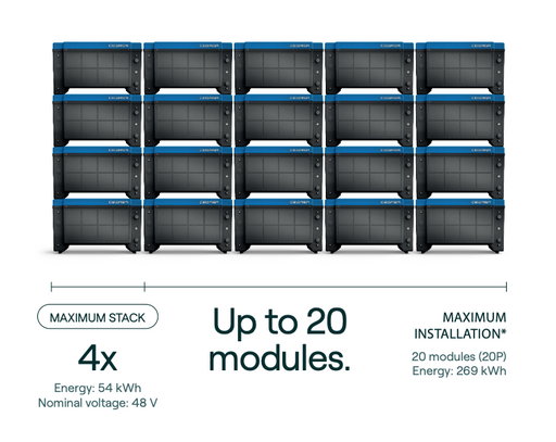
Cegasa E/Bick 48v Lithium Battery
CegasaThe 48v E/Bick LV battery by Cegasa scales to meet your energy storage needs from 13 to 269kWh. With its plug & play connections, the E/Bick i...
View full detailsPylontech US5000 48v LiFePO4 Battery
PylontechThe Pylontech US5000 offers unparalleled reliability and power delivery. This 48V rack-mount sets a standard that other form-factor lithium batteri...
View full detailsVictron Lithium NG Batteries
Victron EnergyBuilding upon the success of Victron's Lithium Smart Series, the NG (Next Generation) series incorporates significant improvements, including: Ad...
View full detailsLithium Battery 12.8V & 25.6V Smart
Victron EnergyAvailable in 12.8 and 25.6V models, Victron Energy's Smart Lithium is a robust, heavy-duty LiFePO4 battery with a high charge and discharge capacit...
View full detailsPylontech 12V LiFePO4 Battery
PylontechBring your mobile application into the 21st century and throw away your shunt with a modern, drop-in battery. Pylontech’s RT12100G31 has it all: It...
View full details
